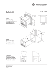
Allen-Bradley panel mounting frame Guide d'installation
PDF
Descarregar
Documento
Bulletin 825
825-FPM
13
(5- 8 +Ð 1
7/1
0
6 +
1
Ð /16
0 )
10 (3/8)
max. 149 (5- 13/16)
10
(3
/8
)
max. 6 mm
(1/4")
OT
OR
MA
NA
GE
R
0
+
Ð
SM
AR
TM
rm
6
/1 8 16
7 3 +0/1
- 1
Ð1
)
Ala
)
All
en-B
rad
ley
Tri
p
Ac
6
tual
/1
t
Cha
ng
e
14
4
Te
s
t
5
max. 159 (6- 1/4)
(
te
4
En
r
Se
ttin
gs
(5
4
lec
t
137 (5- 3/8)
Re
se
6
/1
11
t
1
Se
5
Va
lue
s
(
Se
t
1
1
Rec
orde
-
Einbau
Flush mounting
Montage à encastrement
Montaggio interno
Montaje empotrado
0
(6-
11
/1
6)
ø 6.5 (1/4)
1
5
10
7
0
17
AR
TM
OT
OR
MA
NA
GE
R
1/
2)
SM
(6
-
ley
rm
16
5
-Bra
d
Ala
6)
/1
11
All
en
(6
Aufbau
Surface mounting
Montage en saillie
Montaggio esterno
Montaje en saliente
0(6
))
6
/8
1
7
/
-1
51
(
-
90
º
)
17
Tri
p
Ac
tual
Rec
orde
Se
t
t
Cha
Va
lue
s
Se
lec
t
Se
ng
e
En
ter
ttin
gs
Te
s
Re
22.5º
t
se
t
22.5º
90
º
Technical changes reserved
25.710.913-01/07.2001
Edition 1
Allen-Bradley SMART MOTOR MANAGER
22.5º
Einbaulage
Mounting position
Position de montage
Posizione di montaggio
Posición de montaje
">

Link público atualizado
O link público para o seu chat foi atualizado.