Installation Instructions
FLEX Integra 4 Relay Output Module
(Cat. No. 1793-OW4 and -OW4S)
41355
Module Installation
7KLVPRGXOHPRXQWVRQD',1UDLO,WFRQQHFWVWRDQDGDSWHURUDQRWKHU
)/(;,2RU,QWHJUDPRGXOH1RWH,IXVLQJWKLVPRGXOHZLWK)/(;,2
PRGXOHVGRQRWPRXQWEHWZHHQ)/(;,2PRGXOHV0RXQW,QWHJUD
PRGXOHVWRWKHULJKWRIWKH)/(;,2PRGXOHV7RPRXQWWKLVPRGXOH
5HPRYHWKHFRYHUSOXJLIXVHGLQWKHPDOHFRQQHFWRURIWKHXQLWWR
ZKLFK\RXDUHFRQQHFWLQJWKLVPRGXOH
3RVLWLRQWKHPRGXOHRQWKH[PP',1UDLO$$%SWQR
'5
5RWDWHWKHPRGXOHRQWRWKH',1UDLOZLWKWKHWRSRIWKHUDLOKRRNHG
XQGHUWKHOLSRQWKHUHDURIWKHPRGXOH
A
A
30720-M
FLEX Integra and FLEX I/O are trademarks
of Rockwell Automation
Publication 1793-5.7 - June 1999
2
FLEX Integra 4 Relay Output Module
3UHVVGRZQWRORFNWKHPRGXOHRQWKH',1UDLO
A
41377
,IWKHPRGXOHGRHVQRWORFNLQSODFHXVHDVFUHZGULYHURIVLPLODU
GHYLFHWRPRYHWKHORFNLQJWDEGRZQSUHVVWKHPRGXOHIOXVKZLWKWKH
',1UDLODQGUHOHDVHWKHORFNLQJWDEWRORFNWKHPRGXOHLQSODFH
)LUPO\SXVKWKHPRGXOHLQWRWKHDGMDFHQWPRGXOHWHUPLQDOEDVHXQWLO
WKHXQLWVORFNWRJHWKHU
41371
41370
5HSHDWWKHDERYHVWHSVWRLQVWDOOWKHQH[WPRGXOH
7RUHPRYHDQ,QWHJUDPRGXOH\RXPXVWZRUNIURPWKHULJKWVLGHDQG
UHPRYHRQHPRGXOHDWDWLPH7RGLVHQJDJHDPRGXOHIURPLWV
QHLJKERUSODFHDFRPPRQIODWEODGHGVFUHZGULYHUEHWZHHQWKH
PRGXOHVDQGWXUQWXUQWRVHSDUDWHWKHPRGXOHV
41373
7KHQVOLGHWKHPRGXOHDZD\IURPLWVOHIWQHLJKERUDQGUHOHDVHWKH
ORFNLQJOHYHUWRUHPRYHWKHPRGXOHIURPWKH',1UDLO
Publication 1793-5.7 - June 1999
FLEX Integra 4 Relay Output Module
!
3
$77(17,21 'RQRWUHPRYHWKLVPRGXOHXQGHU
SRZHU5HPRYLQJWKLVPRGXOHXQGHUSRZHUZLOOEUHDNWKH
HOHFWULFDOEDFNSODQHIOH[EXVFRQQHFWLRQV7KLVFDQFDXVH
SHUVRQDOLQMXU\RUSURSHUW\GDPDJHE\
VHQGLQJDQHUURQHRXVVLJQDOWR\RXUV\VWHP
VILHOG
GHYLFHVFDXVLQJXQLQWHQGHGPDFKLQHPRWLRQ
FDXVLQJDQH[SORVLRQLQDKD]DUGRXVHQYLURQPHQW
EUHDNLQJFRPPXQLFDWLRQWRPRGXOHVEH\RQGWKLV
PRGXOH
European Union Directive Compliance
,IWKLVSURGXFWKDVWKH&(PDUNLWLVDSSURYHGIRULQVWDOODWLRQZLWKLQWKH
(XURSHDQ8QLRQDQG(($UHJLRQV,WKDVEHHQGHVLJQHGDQGWHVWHGWRPHHW
WKHIROORZLQJGLUHFWLYHV
EMC Directive
7KLVSURGXFWLVWHVWHGWRPHHW&RXQFLO'LUHFWLYH((&
(OHFWURPDJQHWLF&RPSDWLELOLW\(0&DQGWKHIROORZLQJVWDQGDUGVLQ
ZKROHRULQSDUWGRFXPHQWHGLQDWHFKQLFDOFRQVWUXFWLRQILOH
(1(0&*HQHULF(PLVVLRQ6WDQGDUG3DUW,QGXVWULDO
(QYLURQPHQW
(1(0&*HQHULF,PPXQLW\6WDQGDUG3DUW,QGXVWULDO
(QYLURQPHQW
7KLVSURGXFWLVLQWHQGHGIRUXVHLQDQLQGXVWULDOHQYLURQPHQW
Low Voltage Directive
7KLVSURGXFWLVWHVWHGWRPHHW&RXQFLO'LUHFWLYH((&/RZ9ROWDJH
E\DSSO\LQJWKHVDIHW\UHTXLUHPHQWVRI(13URJUDPPDEOH
&RQWUROOHUV3DUW(TXLSPHQW5HTXLUHPHQWVDQG7HVWV
)RUVSHFLILFLQIRUPDWLRQUHTXLUHGE\(1VHHWKHDSSURSULDWH
VHFWLRQVLQWKLVSXEOLFDWLRQDVZHOODVWKHIROORZLQJ$OOHQ%UDGOH\
SXEOLFDWLRQV
,QGXVWULDO$XWRPDWLRQ:LULQJDQG*URXQGLQJ*XLGHOLQHV)RU1RLVH
,PPXQLW\SXEOLFDWLRQ
$XWRPDWLRQ6\VWHPV&DWDORJSXEOLFDWLRQ%
7KLVHTXLSPHQWLVFODVVLILHGDVRSHQHTXLSPHQWDQGPXVWEHPRXQWHGLQDQ
HQFORVXUHGXULQJRSHUDWLRQWRSURYLGHVDIHW\SURWHFWLRQ
Publication 1793-5.7 - June 1999
4
FLEX Integra 4 Relay Output Module
$77(17,21 'RQRWDWWHPSWWRLQFUHDVHORDGRUZDWWDJH
FDSDELOLW\EH\RQGWKHPD[LPXPUDWLQJE\FRQQHFWLQJRU
PRUHRXWSXWVLQSDUDOOHO7KHVOLJKWHVWYDULDWLRQLQUHOD\
VZLWFKLQJWLPHPD\FDXVHRQHUHOD\WRPRPHQWDULO\VZLWFK
WKHWRWDOORDGFXUUHQW
!
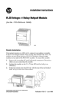
Simplified Schematic of the Relay Module
24V dc
48V dc 120V ac 24V dc 240V ac
Representative examples of relay loads
Relay Load Contact Wiring
dc Return
41366
/RDGSRZHUFDQEHREWDLQHGIURPDYDULHW\RIVRXUFHVDQGFDQUDQJHIURP
9GFWR9DF0DNHFHUWDLQWKDWRQO\9GFLVDSSOLHGWRWKH
PRGXOHSRZHUWHUPLQDOV
!
!
$77(17,21 $SSO\RQO\9GFSRZHUWRWKHSRZHU
WHUPLQDOVRQWKHPRGXOH0DNHFHUWDLQWKDWDOOUHOD\ZLULQJLV
SURSHUO\FRQQHFWHGEHIRUHDSSO\LQJDQ\SRZHUWRWKHPRGXOH
$77(17,21 7RWDOFXUUHQWGUDZWKURXJKWKHPRGXOHLV
OLPLWHGWR$6HSDUDWHSRZHUFRQQHFWLRQVPD\EH
QHFHVVDU\
Publication 1793-5.7 - June 1999
FLEX Integra 4 Relay Output Module
5
Wiring
7KLVPRGXOHLVDYDLODEOHZLWKVW\OHVRIFRQQHFWRUV2:
VFUHZFDJHDQG2:6VSULQJFODPS5HIHUWRWKHZLULQJILJXUH
EHORZ
1793-OW4S
C
0 1 2 3
Ch Ch Ch Ch
V O0 O1 O2 O3 V C
0
1
2
3
4
5
6
Ch
0
Ch
1
Ch
2
Ch
3
1793-OW4
C V O0 O1 O2 O3 V C
0
1
2
3
4
5
6
7
7
A
A
B
8
9
13 14
15
V
V C0 C1 C2 C3 V
10
11
12
V
B
41440
8
9 10 11 12 13 14 15
41441
V V C0 C1 C2 C3 V V
Where: C = common, Cn = relay contact, V = = voltage, On = relay contact
&RQQHFWLQGLYLGXDORXWSXWUHOD\FRQWDFWFXVWRPHUORDGZLULQJWR
QXPEHUHGWHUPLQDOVDVVKRZQLQWKHZLULQJWDEOH7HUPLQDOVDQG
DUHRQHVLGHRIWKHUHOD\FRQWDFWVWHUPLQDOVDQGDUHWKH
RWKHUVLGHRIWKHUHVSHFWLYHUHOD\FRQWDFW
!
$77(17,21 :KHQXVLQJ9SRZHUWRDUHOD\\RX
PXVWFRQQHFWDVQXEEHUDFURVVWKHORDG)DLOXUHWRFRQQHFWD
VQXEEHUDFURVVWKHORDGFDQUHVXOWLQJHQHUDWLRQRI
HOHFWURPDJQHWLFQRLVHZKLFKFRXOGGLVUXSWQHDUE\HOHFWULFDO
HTXLSPHQWLQFOXGLQJ\RXU,QWHJUDV\VWHPRU
)/(;,2V\VWHP8VH$OOHQ%UDGOH\SDUWQXPEHU.$
RU1;VQXEEHU
&RQQHFW9GFSRZHUWRWHUPLQDORQURZ$
&RQQHFW9GFUHWXUQWRWHUPLQDORQURZ$
,IGDLV\FKDLQLQJ9GFIURPWKLVPRGXOHWRWKHQH[W)/(;,QWHJUD
PRGXOHFRQQHFWDMXPSHUIURPWHUPLQDORQWKLVPRGXOHWRWHUPLQDO
RQWKHQH[W)/(;,QWHJUDPRGXOH
,IGDLV\FKDLQLQJ9GFUHWXUQIURPWKLVPRGXOHWRWKHQH[W)/(;
,QWHJUDPRGXOHFRQQHFWDMXPSHUIURPWHUPLQDORQWKLVPRGXOHWR
WHUPLQDORQWKHQH[W,QWHJUDPRGXOH
!
$77(17,21 7RWDOFXUUHQWGUDZWKURXJKWKHPRGXOH¶V
YROWDJHWHUPLQDOVLVOLPLWHGWR$6HSDUDWHSRZHU
FRQQHFWLRQVWRWKHPRGXOHPD\EHUHTXLUHG
Publication 1793-5.7 - June 1999
6
FLEX Integra 4 Relay Output Module
Channel
Output
0
2
10
1
3
11
2
4
12
3
5
13
+24V dc
Terminals 1, 6, 8, 9, 14 and 15 are
internally connected together in the module
24V dc common
Terminals 0 and 7 are internally connected
together in the module.
Indicators
1793-OW4
RELAY OUTPUT
A
41474
B
$ 6WDWXVLQGLFDWRUVVKRZVVWDWXVRILQGLYLGXDOLQSXWV
% ,QVHUWDEOHODEHOIRUZULWLQJLQGLYLGXDOLQSXWGHVLJQDWLRQV
Memory Mappin
Bit/
Word
15
14
13
12
11
10
09
Read
Write
08
07
06
04
03
02
01
00
O3
O2
O1
O0
Reserved
Reserved
Where: IO= Relay output
When bit = 0, output is off; when bit = 1, output is on
Publication 1793-5.7 - June 1999
05
FLEX Integra 4 Relay Output Module
CUL Hazardous Location Approval
Approbation d’utilisation dans des
environnements dangereux par la CUL
CUL certifies products for general use as well as
for use in hazardous locations. Actual CUL
certification is indicated by the product label
as shown below, and not by statements in any
user documentation.
La CUL certifie des produits pour une utilisation
générale aussi bien que pour une utilisation en
environnements dangereux. La certification CUL
en vigueur est indiquée par l'étiquette produit et
non par des indications dans la documentation
utilisateur.
Example of the
CUL
certification
product label
C
US
&/,',9
*3$%&'
7(03
Exemple
d'étiquette de
certification
d'un produit
par la CUL To comply with CUL certification for use in
hazardous locations, the following information
becomes a part of the product literature for this
CUL-certified industrial constrol product.
• This equipment is suitable for use in Class
I, Division 2, Groups A, B, C, D, or
non-hazardous locations only.
• The products having the appropriate CUL
markings (that is, Class I, Division 2, Groups
A, B, C, D) are certified for use in other
equipment where the suitability of
combination (that is, application or use) is
determined by the CUL or the local
inspection office having jurisdiction
C
US
7
&/,',9
*3$%&'
7(03
EPour satisfaire à la certification CUL en
environnements dangereux, les informations
suivantes font partie intégrante de la
documentation des produits de commande
industrielle certifiés.
• Cet équipement ne convient qu’à une
utilisation dans
des environnements de Classe I, Division 2,
Groupes A, B, C, D ou non dangereux.
• Les produits portant le marquage CUL
approprié (c'est-à-dire Classe I, Division 2,
Groupes A, B, C, D) sont certifiés pour une
utilisation avec d'autres équipements, les
combinaisons d’applications et d’utilisation
étant déterminées par la CUL ou le bureau
local d'inspection.
Important: Due to the modular nature of a
Important: De par la nature modulaire des systèmes
programmable control system, the
de commande programmables, le produit
product with the highest temperature
ayant le code de température le plus élevé
rating determines the overall
détermine le code de température global
temperature code rating of a
du système dans un environnement de
programmable control system in a Class
Classe I, Division 2. Le code de
I, Division 2, location. The temperature
température est indiqué sur l'étiquette
code rating is marked on the product
produit.
label as shown.
7HPSHUDWXUHFRGHUDWLQJ
C
US
&/,',9
*3$%&'
7(03
Look for temperature
code rating here.
The following warnings apply to products having
CUL certification for use in hazardous locations.
&RGHGHWHPSpUDWXUH
C
US
&/,',9
*3
$%&'
/ e code de température
est indiqué ici.
Les avertissements suivants s'appliquent aux
produits ayant la certification CUL pour une
utilisation dans des environnements dangereux.
Publication 1793-5.7 - June 1999
8
FLEX Integra 4 Relay Output Module
CUL Hazardous Location Approval
$77(17,21
([SORVLRQ+D]DUG
• Substitution of components may impair
suitability for Class I, Division 2.
• Do not replace components unless power
has been switched off or the area is known
to be non-hazardous.
• Do not disconnect equipment unless power
has been switched off or the area is known
to be non-hazardous.
• Do not disconnect connectors unless
power has been switched off or the area is
known to be non-hazardous. Secure any
user-supplied connectors that mate to
external circuits on this equipment by using
screws, sliding latches, threaded
connectors, or other means such that any
connection can withstand a 15 Newton (3.4
lb.) separating force applied for a minimum
of one minute.
• Batteries must only be changed in an area
known to be non-hazardous.
CUL logo is a registered trademark of the
Underwriters Laboratories.
Publication 1793-5.7 - June 1999
Approbation d’utilisation dans des
environnements dangereux par la CUL
$9(57,66(0(175LVTXHG
H[SORVLRQ
• La substitution de composants peut rendre
ce matériel inadapté à une utilisation en
environnement de
Classe I, Division 2.
• Couper le courant ou s'assurer que
l’environnement est classé non dangereux
avant de remplacer des composants.
• Couper le courant ou s’assurer que
l’environnement est classé non dangereux
avant de débrancher l'équipement.
• Couper le courant ou s'assurer que
l’environnement est classé non dangereux
avant de débrancher les connecteurs. Fixer
tous les connecteurs fournis par l'utilisateur
pour se brancher aux circuits externes de cet
appareil à l 'aide de vis, loquets coulissants,
connecteurs filetés ou autres, de sorte que
les connexions résistent à une force de
séparation de 15 Newtons (1,5 kg - 3,4 lb.)
appliquée pendant au moins une minute.
• S'assurer que l'environnement est classé
non dangereux avant de changer les piles.
Le sigle CUL est une marque déposée de la
Underwriters Laboratories.
FLEX Integra 4 Relay Output Module
9
Specifications - 4 Relay Output Module Cat. No. 1793-OW4 and -OW4S
Module Type
Form A relay output
1793-OW4 - screw-cage terminations
1793-OW4S - spring-clamp terminations
Mounting Location
DIN rail mounting
Number of Channels
1 group of 4
Output Range (at rated power)
Resistive
5-30V dc @ 2.0A
48V dc @ 0.5A
125V dc @ 0.25A
125V ac @ 2.0A
240V dc @ 2.0A
Maximum Power Ratings
(steady state)
Inductive
5-30V dc @ 2.0A; L/R = 7ms
48V dc @ 0.5A; L/R = 7ms
125V dc @ 0.25A; L/R = 7ms
125V ac @ 2.0A; 15A make;
PF = cos θ = 0.4
240V ac @ 2.0A; 15A make;
PF = cos θ = 0.4
Resistive
60W @ 30V dc
24W @ 48V dc
31W @ 125V dc
250W @ 125V ac
480W @ 240V ac
Inductive
60VA @ 30V dc
24VA @ 48V dc
31VA @ 125V dc
250VA @ 125V ac
480VA @ 240V ac
Minimum Contact Load
100μA @ 100mV dc
Off-state Leakage Current
1mA @ 240V ac (through a snubber)
Initial Contact Resistance
30mΩ
Expected Contact Life
100,000 operations minimum at rated loads
Switching Frequency
0.3Hz maximum at rated load
Operate/Release Time
10ms maximum
Bounce Time
1.2ms (mean)
Delay Times
Off to On
On to Off
Isolation Voltage
Between any 2 contacts
Customer load to logic
Customer load to 24V dc
Customer 24V dc to logic
8ms maximum (from valid output ON signal to relay coil
activitation)
26ms (from valid output OFF signal to relay coil
deactivitation)
2550V dc for 1s
2550V dc for 1s
2550V dc for 1s
850V dc for 1s
Fuse Recommendations
3.0A, 250V ac slow blow fuse (Littelfuse pn 239003)
Flexbus Current
70mA maximum
Power Dissipation
5.0W @ 31.2V dc
Thermal Dissipation
17.1 BTU/hr @ 31.2V dc
Publication 1793-5.7 - June 1999
10
FLEX Integra 4 Relay Output Module
Specifications - 4 Relay Output Module Cat. No. 1793-OW4 and -OW4S
Indicators
None
External dc Power Voltage
Current
19.2-31.2V dc (5% ac ripple)
125mA maximum
Dimensions
2.72H x 3.15D x 2.17W
(69H x 80D x 55W)
Environmental Conditions
Operational Temperature
Storage Temperature
Relative Humidity
Shock
Operating
Nonoperating
Vibration
Conductors
Wire Size
Category
0 to +55oC (32 to +131oF)
-40 to +85oC (-40 to +185oF)
5 to 95% noncondensing
Tested to 12g peak acceleration, 11(+1)ms pulse width
Tested to 50g peak acceleration, 11(+1)ms pulse width
Tested 2g @ 10-500Hz per IEC68-2-6
12 gauge (4mm2) stranded wire
3/64 in (1.2mm) maximum insulation
2
Screw Terminal Torque
7-9 lb-in
Agency Certification
(when product is marked)
•
•
•
•
1
CUL Listed
CUL Class I, Division 2 Groups A, B, C and D certified
UL listed
CE marked for all applicable directives
Use this category information for planning conductor routing as described in publication 1770-4.1, “Wiring and
Grounding Guidelines for Noise Immunity.”
Publication 1793-5.7 - June 1999
12
FLEX Integra 4 Relay Output Module
Publication Publication 1793-5.7 - June 1999
Supersedes Publication 1793-5.7 - August 1998
PN 955132-20A
© (1999) Rockwell International Corporation.Printed in USA
">